I2C example

I2C (Inter-Integrated Circuit) communication is a protocol widely used for connecting microcontrollers and peripherals. This tutorial demonstrates how to implement I2C communication between two Arduino Uno boards in Proteus. We'll configure one Arduino as the Master and the other as the Slave. The Master sends data to the Slave, and the Slave responds by displaying the data on its Serial Monitor and blinking an LED.
Hardware Requirements
2 Arduino Uno boards
A computer with Proteus simulation software
Virtual connections in Proteus for the I2C communication (SDA and SCL)
I2C Overview
The I2C protocol uses two wires for communication:
SDA (Serial Data Line): Transfers data between devices.
SCL (Serial Clock Line): Synchronizes the communication.
Each device in the network has a unique address. In our example, the Slave Arduino has been assigned the address 6.
The Master Code
Below is the code for the Master Arduino, which transmits data to the Slave.
#include <Wire.h>
int LED = 13; // Initialize pin 13 to drive LED
void setup() {
Wire.begin(); // Join I2C bus (address optional for Master)
}
byte x = 0;
void loop() {
Wire.beginTransmission(6); // Transmit to device #6
Wire.write("x is"); // Sends five bytes
Wire.write(x); // Sends one byte
Wire.endTransmission(); // Stop transmitting
x++;
delay(500);
}
Explanation:
The
Wire.begin()function initializes the I2C bus in Master mode.The
Wire.beginTransmission(6)function specifies the Slave address (6).Wire.write()sends a message and an incrementing value (x) to the Slave.The
delay(500)function provides a half-second interval between transmissions.
The Slave Code
Below is the code for the Slave Arduino, which receives and processes data from the Master.
#include <Wire.h>
int LED = 13;
void setup() {
pinMode(LED, OUTPUT); // Set LED pin as output
Wire.begin(6); // Join I2C bus with address #6
Wire.onReceive(receiveEvent); // Register receive event
Serial.begin(9600); // Start Serial Monitor for output
}
void loop() {
delay(100); // Wait for data from Master
}
void receiveEvent(int howMany) {
while (1 < Wire.available()) { // Loop through all but the last byte
char c = Wire.read(); // Receive byte as a character
Serial.print(c); // Print the character to Serial Monitor
digitalWrite(LED, HIGH); // Turn LED on
delay(1000);
digitalWrite(LED, LOW); // Turn LED off
delay(500);
}
int x = Wire.read(); // Receive the last byte as an integer
Serial.println(x); // Print the integer to Serial Monitor
}
Explanation:
The
Wire.begin(6)function assigns address6to the Slave.The
Wire.onReceive(receiveEvent)function registersreceiveEventas the callback for received data.The
receiveEventfunction processes incoming data:Characters are printed to the Serial Monitor.
The LED blinks with each received message.
The last byte (an integer) is printed separately.
Simulation in Proteus
Set Up the Components:
Place two Arduino Uno boards in Proteus.
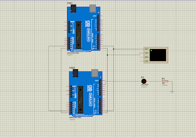
Connect the SDA (A4) and SCL (A5) pins of both boards.
Add a virtual terminal to display Serial Monitor output by rightclicking and selecting PLace > Virtual instrument > Virtul terminal


Connect an LED to pin 13 of the Slave Arduino.
Load the Codes:
Load the Master and Slave codes into the respective Arduinos.
Run the Simulation:
Start the simulation in Proteus.
Observe the data being sent from the Master to the Slave.
Watch the LED blink on the Slave and verify the output in the Serial Monitor.

EmbedLab Team
Embedded systems engineer and educator. Writes weekly tutorials at EmbedLab to help beginners ship real hardware.
Related projects
Top 5 IoT Projects with Arduino UNO & ESP32 — Blynk, Wi-Fi & Smart Home Tutorials (2026)
The top 5 IoT projects every Arduino UNO and ESP32 maker should build in 2026 — Blynk IoT control, Wi-Fi blink, ESP-WROOM-32 dev board guide, ESP32 Proteus 8 simulation and an Arduino smart home parking system. Each pick links to the full tutorial with free Arduino IDE code, library and wiring.
Blynk IoT with Arduino UNO & ESP32 — Free Arduino IDE, Library & App Tutorial
Complete Blynk IoT tutorial for Arduino UNO and ESP32 Arduino: install the Arduino IDE, add the Blynk Arduino library, wire LEDs, LCD and sensors, and control everything from the Blynk app over Wi-Fi — a free, beginner-friendly Arduino IoT project.

Arduino UNO Blink IoT Guide — ESP32 Arduino, Blynk App & Arduino IDE Code
Complete Arduino UNO Blink IoT guide using ESP32 Arduino and the Blynk app: free Arduino IDE code, Arduino library and LED wiring — the easiest Arduino IoT project for beginners to download and try online.

How to Control LEDs Using Blynk and Arduino Uno: A Complete Guide
How to Control LEDs Using Blynk and Arduino Uno: A Complete Guide Controlling LEDs remotely using Blynk and an Arduino Uno is a simple yet powerful project for IoT (Internet of Things) enthusia
Proteus 8 Blynk
Connect Proteus 8 with Blynk Using Arduino: A Complete Step-by-Step Guide Looking to seamlessly connect Proteus 8 with Blynk using Arduino ? This detailed tutorial covers everything from setting up a