Arduino Multiplexer — 74HC595 & 4051 Wiring, Code & Projects
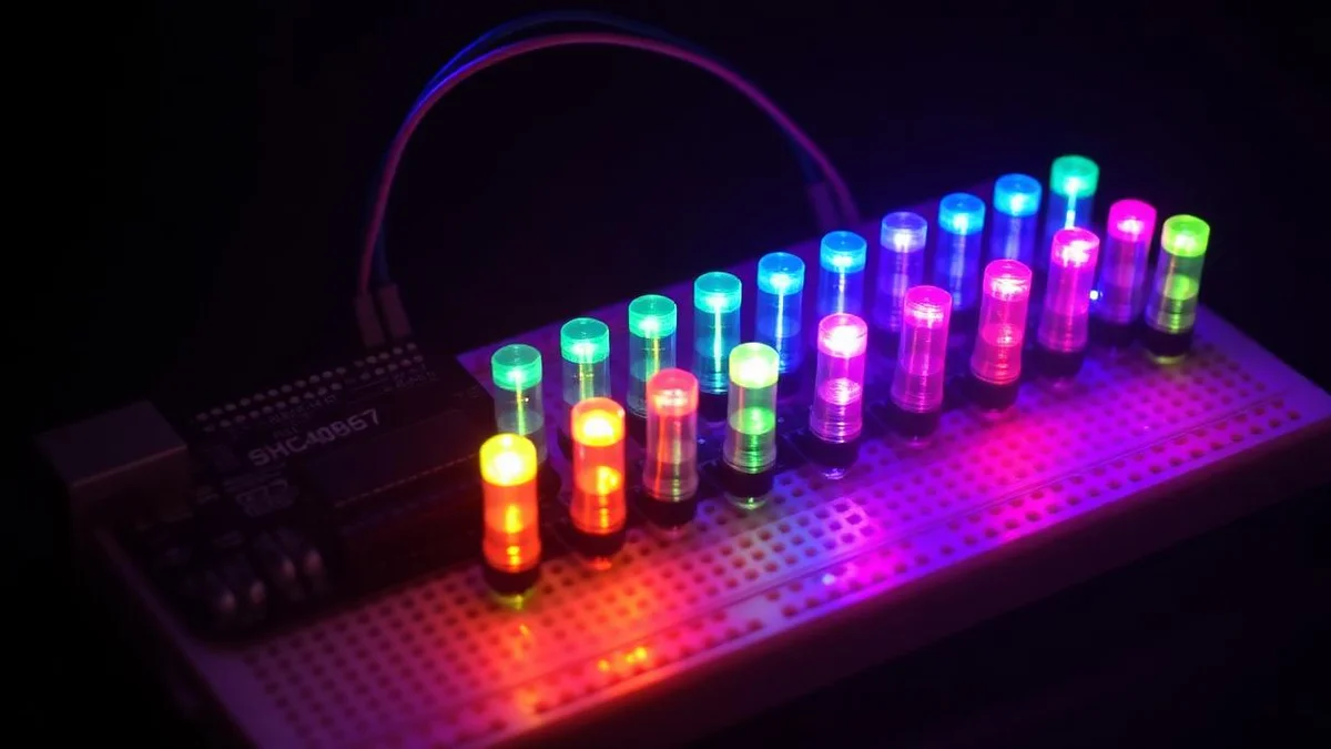
An Arduino Multiplexer lets you drive dozens of LEDs, buttons or sensors from just a few Arduino Uno pins. In this project we wire both the 74HC595 shift register and the 4051 analog multiplexer, walk through the Arduino IDE code, and simulate everything in Proteus so you can scale I/O without buying a Mega.

Are you ready to control eight LEDs with just three Arduino pins? Then a multiplexer is your secret weapon. In fact, using a 3-to-8 multiplexer like the 74HC138, you can build dynamic lighting effects without crowding your microcontroller’s I/O. Moreover, when you combine it with Pulse-Width Modulation (PWM), you unlock smooth brightness control and stunning animations—all with minimal wiring.
This guide walks you through three beginner-friendly Arduino multiplexer LED projects: Brightness Decrease, Ping Pong, and Random LED Burst. Each one teaches core concepts like binary channel selection, PWM dimming, and real-time control. Therefore, whether you’re new to electronics or refreshing your skills, these hands-on examples will light up your learning path.
Need this built for you? I do custom Arduino, ESP32 and Proteus projects from $15.
Why Use a Multiplexer for Arduino LED Control?
A multiplexer solves a common problem: limited digital pins. For example, the Arduino Uno has only 14 digital I/O pins. But what if you want to control 8, 16, or even 32 LEDs? That’s where a 3-to-8 multiplexer shines.
Specifically, a 3-to-8 multiplexer uses just three select pins to activate one of eight output channels at a time. Consequently, you reduce pin usage from eight to three—a 62% savings. Additionally, this simplifies your breadboard layout and cuts down on jumper wires.
But that’s not all. When paired with PWM, a multiplexer enables dynamic brightness control across multiple LEDs. As a result, you can create smooth fades, bouncing lights, or random bursts—effects that feel alive and responsive.
Essential Components for Arduino Multiplexer LED Projects
Before you start, gather these basic parts. First, you’ll need an Arduino Uno or any compatible board. Second, get a 3-to-8 multiplexer IC—such as the 74HC138. Third, collect eight LEDs (any color works).
Also, prepare eight current-limiting resistors (220Ω to 330Ω). These protect your LEDs from burning out. Furthermore, you’ll need a breadboard and jumper wires for connections. Finally, use a standard USB cable to power and program your Arduino.
Optionally, add a USB-to-Serial module for advanced debugging. However, for these beginner projects, the built-in Serial Monitor in the Arduino IDE is more than enough.
How to Wire the 3-to-8 Multiplexer to Arduino
Wiring is straightforward once you understand the pin roles. The multiplexer has three key sections: select inputs (A, B, C), output channels (Y0–Y7), power (VCC/GND), and an enable pin (often grounded for always-on mode).
First, connect the select pins A, B, and C to Arduino digital pins 2, 3, and 4. Next, link VCC to the Arduino’s 5V pin and GND to ground. Then, attach each output (Y0 through Y7) to an LED anode through a 220Ω resistor. After that, connect all LED cathodes directly to GND.
💡 Tip: Always double-check resistor values. Too low, and your LED may overheat. Too high, and it will appear dim. Also, ensure your multiplexer runs on 5V logic to match the Arduino’s signal levels.
Once wired, your circuit will let the Arduino choose which LED lights up—and how brightly—using just four pins total (three for selection, one for PWM).
Project 1: Smooth Brightness Decrease LED Effect
This first project creates a calming wave of light that dims one LED at a time. It’s perfect for mood lighting or visual feedback systems. The effect uses PWM to gradually reduce brightness from 255 (full) to 0 (off).
Here’s how it works: the Arduino loops through channels 0 to 7. For each, it selects the LED using binary signals on pins 2–4. Then, it slowly lowers the PWM value on pin 5. As a result, each LED fades out smoothly before the next one starts.
int selectPins[] = {2, 3, 4}; // A, B, C pins

void selectChannel(int channel) {
for (int i = 0; i < 3; i++) {
digitalWrite(selectPins[i], (channel >> i) & 1);
}
}

void setup() {
for (int i = 0; i < 3; i++) {
pinMode(selectPins[i], OUTPUT);
}
}

void loop() {
for (int channel = 0; channel < 8; channel++) {
selectChannel(channel);
for (int brightness = 255; brightness >= 0; brightness -= 5) {
analogWrite(5, brightness); // PWM pin
delay(50);
}
}
}
Notice the selectChannel function. It converts the channel number (0–7) into a 3-bit binary pattern. For instance, channel 5 becomes 101, so pin 2 = 1, pin 3 = 0, pin 4 = 1. This binary addressing is the core of multiplexing.
Meanwhile, analogWrite(5, brightness) controls intensity. Because pin 5 supports PWM, it simulates analog output by rapidly switching on and off. The human eye sees this as smooth dimming.
Project 2: Ping Pong LED Bounce Effect
Next, create a classic “ping pong” animation where light travels back and forth like a bouncing ball. This project builds on the first but adds direction control and timing for rhythm.
The code first lights LEDs from 0 to 7 (left to right). Then, it reverses and goes from 7 to 0 (right to left). Each LED flashes at full brightness for 100 milliseconds. Therefore, the motion feels fluid and continuous.
int selectPins[] = {2, 3, 4};

void selectChannel(int channel) {
for (int i = 0; i < 3; i++) {
digitalWrite(selectPins[i], (channel >> i) & 1);
}
}

void setup() {
for (int i = 0; i < 3; i++) {
pinMode(selectPins[i], OUTPUT);
}
pinMode(5, OUTPUT);
}

void loop() {
// Forward loop (0 to 7)
for (int channel = 0; channel < 8; channel++) {
selectChannel(channel);
analogWrite(5, 255);
delay(100);
analogWrite(5, 0);
}
// Reverse loop (7 to 0)
for (int channel = 7; channel >= 0; channel--) {
selectChannel(channel);
analogWrite(5, 255);
delay(100);
analogWrite(5, 0);
}
}
In this version, the LED turns on fully (255), waits, then turns off (0). This on/off burst creates a sharp, clear bounce—ideal for attention-grabbing displays or game indicators.
Additionally, you can tweak the delay to speed up or slow down the animation. For example, 50ms makes it frantic; 200ms makes it relaxed. Experiment to match your project’s mood.
Project 3: Random LED Burst Effect
Finally, add excitement with unpredictable flashes. This “Random LED Burst” effect lights a random LED every 150 milliseconds, creating a lively, chaotic display—great for alarms, alerts, or party lights.
The key here is the random() function. But to avoid the same sequence every time, the code uses randomSeed(analogRead(0)). Since analog pin 0 is unconnected, it picks up electrical noise, giving a unique seed on startup.
int selectPins[] = {2, 3, 4};

void selectChannel(int channel) {
for (int i = 0; i < 3; i++) {
digitalWrite(selectPins[i], (channel >> i) & 1);
}
}

void setup() {
for (int i = 0; i < 3; i++) {
pinMode(selectPins[i], OUTPUT);
}
pinMode(5, OUTPUT);
randomSeed(analogRead(0));
}

void loop() {
int channel = random(8);
selectChannel(channel);
analogWrite(5, 255);
delay(100);
analogWrite(5, 0);
delay(50);
}
Each loop picks a random number from 0 to 7. Then, it activates that channel and flashes the LED. The short off-delay (50ms) keeps the pace energetic without overwhelming the viewer.
Moreover, you can expand this idea. For instance, use two multiplexers to control 16 LEDs. Or, add a button to trigger bursts only when pressed. The possibilities grow as you master the basics.
How Multiplexing Works: A Simple Explanation
At its core, multiplexing is about sharing resources. Instead of giving each LED its own pin, you share one PWM pin and use the multiplexer to “switch” which LED receives power at any moment.
The Arduino sends a 3-bit address (like 000, 001, 010…) to the select pins. The multiplexer reads this and activates the matching output (Y0 for 000, Y1 for 001, etc.). Only one output is active at a time—but if you switch fast enough, all LEDs appear to stay on.
In our projects, we don’t rely on persistence of vision because we light one LED at a time intentionally. However, in more advanced setups (like LED matrices), rapid switching creates the illusion of multiple LEDs glowing simultaneously.
Tips for Success with Arduino Multiplexer Projects
To avoid common mistakes, follow these best practices. First, always use current-limiting resistors. LEDs without resistors can draw too much current and damage the multiplexer or Arduino.
Second, verify your multiplexer’s logic. The 74HC138 activates outputs with a LOW signal, but some variants behave differently. Check the datasheet to confirm. Third, use PWM-capable pins (3, 5, 6, 9, 10, or 11 on Uno) for brightness control.
Fourth, keep wires short and tidy. Long jumper wires can pick up noise, causing flickering or missed signals. Fifth, test one LED at a time before running full animations. This helps isolate wiring errors quickly.
Finally, comment your code. Functions like selectChannel make your logic reusable. Later, you can add features like speed control or pattern selection with minimal changes.
Expand Your Skills: Next Steps After These Projects
Once you’ve mastered these three effects, try combining them. For example, start with a ping pong bounce, then switch to random bursts when a sensor is triggered. Or, fade all LEDs in unison using a single brightness variable.
You can also interface a potentiometer to adjust speed or brightness in real time. Just read an analog input and map it to delay() or analogWrite() values. This adds user control without extra pins.
Moreover, consider chaining two 3-to-8 multiplexers to control 16 LEDs with only four Arduino pins (three select + one enable). This scales your projects while keeping the design clean.
In the long run, these skills apply to real-world systems like dashboard indicators, smart lighting, or interactive art installations. So, keep experimenting—every line of code brings you closer to building something amazing.
Final Thoughts: Light Up Your Arduino Journey
These Arduino multiplexer LED projects prove that powerful effects don’t require complex hardware. With just a few components, you’ve learned to save pins, control brightness, and create dynamic animations.
Whether you’re building a mood lamp, a game console, or a science fair display, multiplexing gives you more control with less clutter. So, upload the code, wire the circuit, and watch your LEDs come alive—one channel at a time.
Remember: the best way to learn is by doing. Try modifying the delay times, adding colors, or syncing lights to sound. Before long, you’ll design your own effects from scratch.
Stuck on your own build? Send me your Arduino / ESP32 / Proteus project on Fiverr — from $15, you don't pay if it doesn't work.
The Engineer Post
Embedded systems engineer and educator. Writes weekly tutorials at EmbedLab to help beginners ship real hardware.
Related projects

Extend Arduino UNO Inputs & Outputs — 74HC595, Multiplexer & LCD Tutorial
Extend the inputs and outputs of your Arduino UNO with 74HC595 shift registers and 4051/4067 multiplexers: free Arduino IDE code, ready-to-use Arduino library, LED matrix and LCD wiring, plus the same circuits for Arduino Nano and Arduino Mega.

Interface SPI EEPROM with Arduino UNO — Free Arduino IDE Code & Library
How to interface an SPI EEPROM with Arduino UNO step by step: free Arduino IDE code, Arduino library, full wiring map — easily ported to Arduino Nano, Arduino Mega and ESP32 Arduino.
30+ Arduino UNO Projects for Beginners — Free Arduino IDE Code, LED & LCD
30+ beginner Arduino UNO projects with free Arduino IDE code, Arduino library examples, LED and LCD circuits, plus Arduino Nano, Arduino Mega and ESP32 Arduino tutorials — perfect first Arduino project ideas to download and build today.
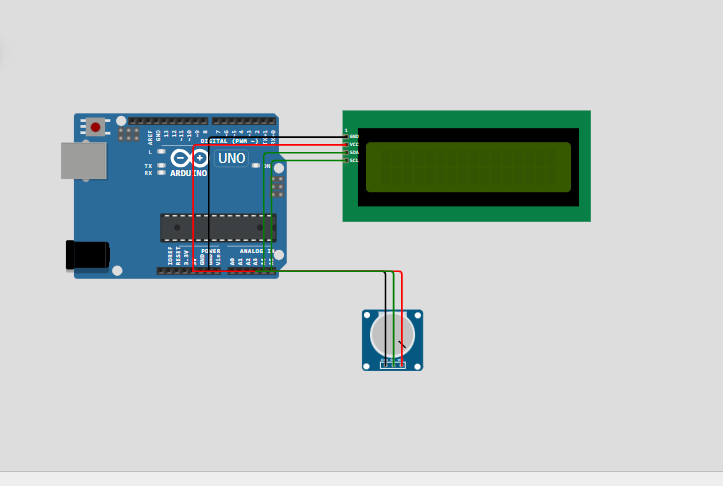
5 Simple Arduino UNO Projects for Beginners — Free Arduino IDE Code Step by Step
5 simple Arduino UNO projects for beginners to learn electronics step by step: free Arduino IDE code, Arduino library, LED, LCD and sensors — perfect first Arduino project ideas that also run on Arduino Nano, Arduino Mega and ESP32 Arduino.
Arduino UNO Smart Parking System (8 Spots) — LCD, IR Sensors & Arduino IDE Code
Build an Arduino UNO smart parking system with 8 spots: IR sensors, LCD display, servo gate, free Arduino IDE code and Arduino library — easily portable to Arduino Mega and ESP32 Arduino for IoT upgrades.