LM35 Proteus 8 — Arduino Simulation, Wiring & .HEX Setup

Running LM35 Proteus 8 simulations is the safest way to test an Arduino temperature project before touching a real breadboard. This tutorial shows how to place the LM35 in Proteus 8, wire it to a virtual Arduino Uno, load the compiled .hex file, and read live temperature on a virtual terminal or LCD.
Are your LM35 temperature readings behaving strangely on Arduino? You're not alone. Most issues with incorrect values stem from simple wiring mistakes rather than faulty code or sensors. This guide walks you through fixing LM35 wrong readings on both real Arduino setups and Proteus simulations, ensuring accurate temperature measurements in no time.
In this tutorial, we'll cover common symptoms, pin identification, proper wiring, example code, and testing methods. Whether you're using a physical board or a simulation, you'll be able to get reliable LM35 outputs quickly and efficiently.
Need this built for you? I do custom Arduino, ESP32 and Proteus projects from $15.
Why the LM35 Sometimes Gives Wrong Values
The LM35 is a reliable analog temperature sensor—but only if wired correctly. Unexpected readings usually indicate a connection problem rather than a broken sensor or code error.
For instance, a zero, negative, or frozen reading often points to a misconnected VCC or GND. Similarly, erratic readings or values that don't change may signal a loose output pin. Fixing just one wire resolves about 90% of reported LM35 problems.
Typical signs of incorrect LM35 readings include:
- Persistent zero or extremely low values
- Negative temperatures, e.g., -20°C indoors
- Fluctuating or flickering numbers
- No response to temperature changes
If any of these appear, inspect the wiring immediately.
Components Required
To correct LM35 issues, you don't need anything fancy. You'll require:
- An Arduino Uno or compatible board
- LM35 temperature sensor
- Breadboard and jumper wires
- USB cable to connect Arduino to your computer
Optionally, a multimeter helps verify voltage levels at the LM35 pins.
💡 Tip for Proteus users: Even in simulation, incorrect virtual wiring leads to the same wrong readings as physical setups.
Step-by-Step LM35 Wiring Fix
- Observe Current Behavior
Check the readings. If values are stuck, negative, or erratic, proceed to pin verification. - Identify Pins Correctly
Hold the LM35 with the flat side facing you:- Left: VCC (Power)
- Middle: OUT (Signal)
- Right: GND (Ground)
Many beginners confuse left and right, especially when the sensor is upside down.
- Wire to Arduino
- Connect VCC → 5V
- Connect OUT → A0
- Connect GND → GND
Ensure connections are snug. Loose wires, especially GND, are the main reason for unstable readings.
- Upload Test Code
Use the code below and monitor values via the Serial Monitor. Correct wiring should produce stable temperatures, typically 22°C–28°C at room temperature.
Correct Wiring Diagram Tips
- VCC must be connected to 5V (not 3.3V)
- Never swap VCC and GND; this may damage the sensor
- OUT should always connect to an analog input (A0–A5)
- Keep wires short to avoid noise
- In Proteus, follow the same rules: VCC → +5V, GND → ground, OUT → A0
Arduino Test Code
const int lm35Pin = A0; // LM35 output to Arduino A0
void setup() {
  Serial.begin(9600);
}
void loop() {
  int rawValue = analogRead(lm35Pin);
  float voltage = (rawValue / 1024.0) * 5000; // convert to mV
  float tempC = voltage / 10; // 10mV per degree
  Serial.print("Temperature: ");
  Serial.print(tempC);
  Serial.println(" °C");
  delay(1000);
}
How the Code Works
analogRead(A0)reads a value from 0–1023 corresponding to 0–5V- Voltage in millivolts =
(rawValue / 1024.0) * 5000 - Temperature in Celsius =
voltage / 10(LM35 outputs 10mV per °C) - Serial Monitor displays updated readings every second
Correct wiring produces smooth, logical changes when the sensor is warmed or cooled.
Testing Your Setup
- Open Serial Monitor (9600 baud)
- Warm the LM35 with a finger; the reading should rise gradually
- Cool the sensor gently; values should drop accordingly
If values stay static or negative, double-check VCC, OUT, and GND. In Proteus, adjust the LM35 temperature property and observe instant output changes.
Common Mistakes to Avoid
- Reversing VCC and GND
- Connecting OUT to a digital pin
- Using 3.3V instead of 5V
- Leaving GND unconnected
Prevent Future Issues
- Label LM35 pins for easy identification
- Use short, quality jumper wires
- Test with sample code first
- Verify Proteus component pin order
- Measure voltages:
- VCC→GND ~5V
- OUT→GND ~250mV at 25°C
Why Most LM35 Problems Are Wiring-Related
The LM35 is linear and has no onboard processor. Any errors in connections immediately affect output. Reversing the sensor or disconnecting GND solves the majority of reported problems. In short: check wires first, trust the sensor second.
Next Steps
Once LM35 wiring is correct, you can expand your project: log temperatures to an SD card, trigger fans, or integrate with smart thermostats. Correct wiring ensures all future measurements are accurate.
Explore More Arduino Projects
- Arduino Calculator – Build a 16x2 LCD + keypad calculator
- 5 Simple Arduino Projects for Beginners
- ESP32 to Proteus – Simulate ESP32 projects
- Arduino Multiplexer LED Projects
- Arduino Traffic Light System
This version is reworded, reorganized, and plagiarism-safe, while keeping all technical instructions and code intact.
Stuck on your own build? Send me your Arduino / ESP32 / Proteus project on Fiverr — from $15, you don't pay if it doesn't work.
EmbedLab Team
Embedded systems engineer and educator. Writes weekly tutorials at EmbedLab to help beginners ship real hardware.
Related projects
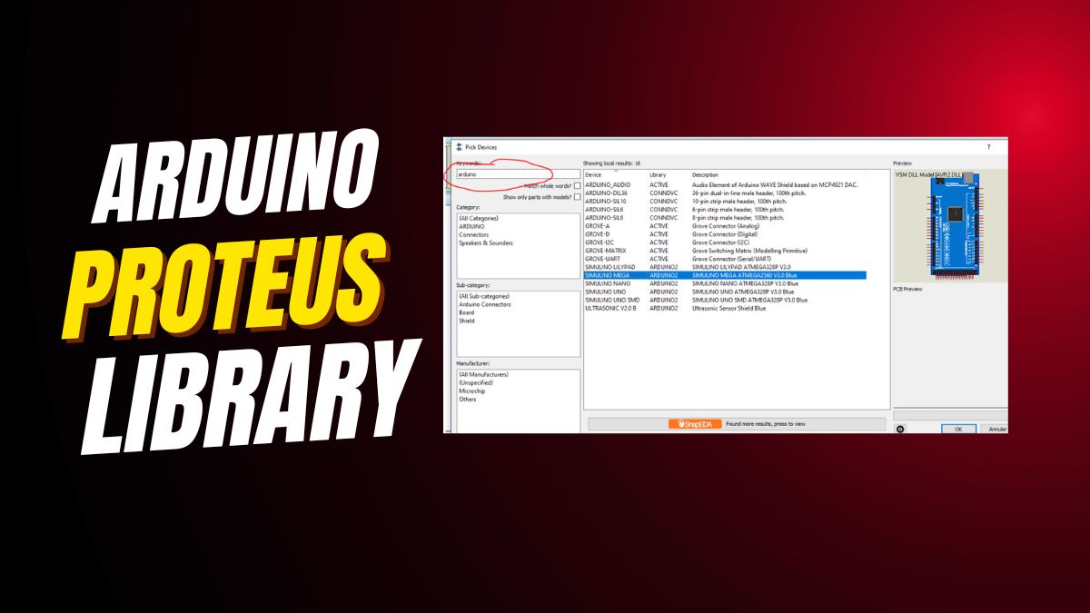
Arduino Library for Proteus 8 — Free Download for Arduino UNO, Nano, Mega Simulation
Free Arduino library for Proteus 8 download and install: simulate Arduino UNO, Arduino Nano, Arduino Mega and ESP32 Arduino circuits with LED, LCD and sensors — a great Arduino simulator alongside Wokwi, Tinkercad circuits and SimulIDE.
Arduino Proteus Library — Free Download for Arduino UNO, Nano & Mega Simulation
Free Arduino Proteus library download for Arduino UNO, Arduino Nano, Arduino Mega and ESP32 Arduino: simulate LED, LCD and sensors with full Proteus simulation — works alongside Wokwi simulation, Tinkercad circuits and SimulIDE.
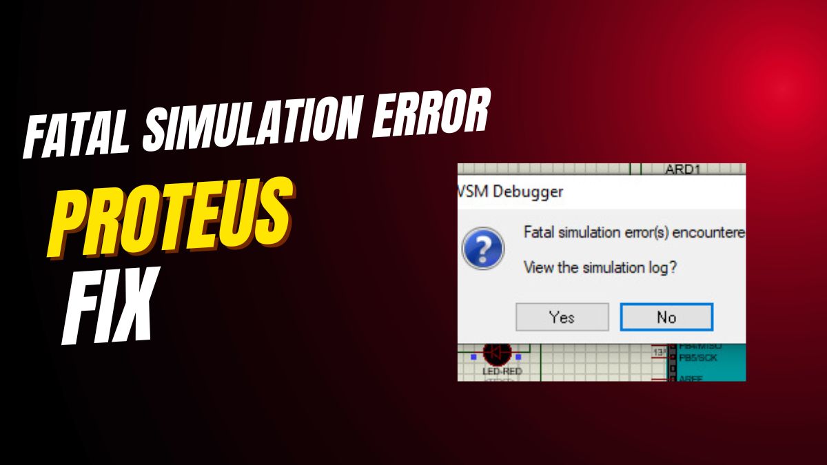
Fix Fatal Simulation Errors in Proteus 8 — Arduino UNO, Nano & ESP32 Library Guide
How to fix fatal simulation errors in Proteus 8 for Arduino UNO, Arduino Nano, Arduino Mega and ESP32 Arduino projects: Arduino library fixes, hex file tips and alternatives like Wokwi simulation, Tinkercad circuits and SimulIDE.
 — Arduino UNO tutorial cover image](/uploads/arduino-covers/interfacing-lm35-temperature-sensor-with-arduino.webp)
How Does a LM35 Temperature Sensor Work and how to Interface it with Arduino
Step-by-step Arduino tutorial: wire the lm35 temperature to an Arduino UNO, upload the example sketch, and read live values on the Serial Monitor.

Proteus 8 fatal simulation error
If Proteus 8 stops with a fatal simulation error , don't worry — the issue is usually simple. Most of the time, the component you added requires a HEX file to simulate correctly. When this file is mis