ESP32 LED Blink in Proteus 8 Simulation — Arduino IDE ESP32 WROOM DevKit Tutorial
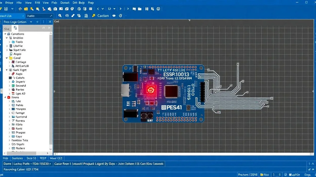

ESP32 LED Blink Simulation — Arduino IDE ESP32 WROOM in Proteus 8
Before you start, grab the ESP32 Proteus library here: how to download the ESP32 library for Proteus 8. It works for the ESP32 WROOM, ESP32 DevKit and ESP32 dev board variants from Espressif.
This ESP32 LED blink simulation in Proteus 8 is the perfect first project for anyone learning Arduino ESP32, Arduino IDE ESP32 programming, or comparing Wokwi simulation, Proteus simulation and other ESP32 simulator tools. You'll add the ESP32 WROOM / ESP32 DevKit module, wire a red LED with a 220Ω resistor to the right ESP32 pinout (GPIO2), and flash a blink sketch through the Espressif ESP32 Arduino core. The same approach works for the ESP32-S3, ESP32-C3, and ESP32 Mini dev boards, and unlocks the Wi-Fi and Bluetooth features the ESP32 module is famous for.
Why Simulate ESP32 LED Blink in Proteus8?
First of all, simulation saves time and money. You don’t need physical hardware to test your ideas. Also, Proteus8 lets you visualize how your circuit behaves before building it. As a result, you avoid common mistakes like wrong wiring or incorrect resistor values. Most importantly, this method helps you learn faster and safer.
Step 1: Add the ESP32 Library to Proteus8
Before you start, make sure you’ve added the ESP32 library to Proteus8. If you haven’t, check the creator’s earlier video for exact steps. Once the library is installed, Proteus8 will recognize the ESP32 board. Consequently, you can drag and drop it into your workspace without issues.
After that, open Proteus8 and click the component mode button. Then, type “ESP32” in the search bar. You’ll see a result labeled something like “ESP32 Dev Module” or “WROOM-32.” Select it and place it on the design area. This is your main microcontroller for the simulation.
Step 2: Add the Red LED and 220-Ohm Resistor
Next, you need two basic parts: a red LED and a resistor. In Proteus8, go back to the component library. Search for “LED-RED” and place it on the sheet. Then, search for “RESISTOR” and choose a generic one. After placing it, double-click the resistor to set its value to 220 ohms.
Why 220 ohms? Because it limits current safely for a standard red LED powered by 3.3V (ESP32’s logic level). Without it, too much current could damage the LED or the ESP32 pin. Therefore, always use a current-limiting resistor—220Ω is perfect for this setup.
Step 3: Wire the Circuit Correctly
Now, connect the components properly. First, link one leg of the resistor to GPIO2 (often the built-in LED pin on many ESP32 boards). Then, connect the other end of the resistor to the anode (longer leg) of the red LED. After that, connect the cathode (shorter leg) of the LED to a ground (GND) pin on the ESP32.
Additionally, ensure all ground terminals are connected. In Proteus8, use the ground symbol from the toolbar and attach it to the LED’s cathode. This completes the circuit. As a result, current can flow from GPIO2 → resistor → LED → ground when the pin is HIGH.
Step 4: Write the Arduino Code for LED Blink
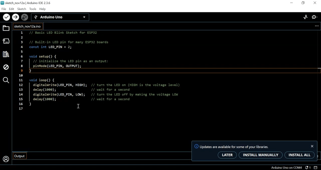
For the coding part, open the Arduino IDE. Even though you’re simulating an ESP32, you’ll use the Arduino framework because it’s beginner-friendly. First, install the ESP32 board package via Tools > Board > Boards Manager. Search for “ESP32” and install the official package by Espressif Systems.
After installation, select “ESP32 Dev Module” (not Arduino Uno—this was a slip in the original video). Then, write or paste the following code. This sketch makes the LED blink once per second:
// Basic LED Blink Sketch for ESP32

// Built-in LED pin for many ESP32 boards
const int LED_PIN = 2;

void setup() {
  // Initialize the LED pin as an output:
  pinMode(LED_PIN, OUTPUT);
}

void loop() {
  digitalWrite(LED_PIN, HIGH); // turn the LED on (HIGH is the voltage level)
  delay(1000);              // wait for a second
  digitalWrite(LED_PIN, LOW);  // turn the LED off by making the voltage LOW
  delay(1000);              // wait for a second
}
Note: GPIO2 is commonly used as the built-in LED pin on many ESP32 development boards. However, always verify your specific board’s pinout. If your LED connects to a different GPIO, change `LED_PIN` accordingly.
Step 5: Compile and Export the Binary File
Once your code is ready, click the Verify (checkmark) button to compile it. If there are no errors, go to Sketch > Export Compiled Binary. This creates a .bin file in your sketch folder. Meanwhile, save your sketch with a clear name like “ESP32_LED_Blink_Tutorial” to avoid confusion later.
After exporting, locate the .bin file. Usually, it appears in the same folder as your .ino file. You’ll need this file to load into the ESP32 component in Proteus8. So, remember where you saved it!
Step 6: Load the Code into Proteus8 Simulation
Return to Proteus8. Double-click the ESP32 component to open its properties. In the Program File field, browse and select your exported .bin file. Also, set the crystal frequency to 40MHz (standard for ESP32). Then, click OK to apply the settings.
Next, click the Play button (simulate) in Proteus8. If everything is correct, the red LED will start blinking—one second on, one second off. If it doesn’t work, check your wiring, resistor value, and that the correct .bin file is loaded.
Troubleshooting Common ESP32 Simulation Issues
Sometimes the LED won’t blink. First, confirm you selected the right board in Arduino IDE (ESP32 Dev Module, not Arduino Uno). Secondly, ensure the .bin file matches your code. Moreover, verify that GPIO2 is connected—not all ESP32 pins support output the same way.
Also, make sure Proteus8 has the correct ESP32 model file (usually a .pdsprj or .IDX file included with the library). Without it, simulation fails. If needed, re-download the ESP32 Proteus library from a trusted source.
Benefits of Using a 220-Ohm Resistor with LED
Why not use 100 ohms or 1k ohms? Because 220 ohms strikes the right balance. ESP32 operates at 3.3V, and a red LED typically drops 1.8–2.2V. Using Ohm’s Law (I = V/R), a 220Ω resistor limits current to about 5–7mA—safe for both the LED and the microcontroller.
Higher resistance (e.g., 1kΩ) makes the LED dim. Lower resistance (e.g., 100Ω) risks drawing too much current, possibly damaging the ESP32. Therefore, 220Ω is the recommended value for red LEDs in 3.3V circuits.
Expand Your Project: Add More Features
Once the basic blink works, try adding features. For instance, use two LEDs on different pins and blink them alternately. Or, replace `delay()` with `millis()` for non-blocking code. Furthermore, simulate button inputs to control the LED—great practice for real-world projects.
You can also simulate sensors like DHT11 or ultrasonic modules later. The same workflow applies: design circuit → write code → export .bin → load into Proteus8. As a result, your simulation skills grow steadily.
Final Tips for Success
Always double-check connections before simulating. Also, name your files clearly to avoid loading the wrong .bin. Moreover, keep your Arduino IDE and Proteus8 updated for best compatibility. Finally, refer to official ESP32 pinout diagrams—never assume pin functions.
By following this guide, you’ve taken a solid first step into embedded systems. Whether you’re a student, hobbyist, or educator, simulating ESP32 projects builds real understanding. So, keep experimenting and learning!
Don’t forget to like, subscribe, and visit the creator’s website for more tutorials. Your support helps bring more beginner-friendly content. Thank you—and happy simulating
The Engineer Post
Embedded systems engineer and educator. Writes weekly tutorials at EmbedLab to help beginners ship real hardware.
Related projects

ESP32 Proteus 8 Simulation — Free ESP32 Library, Arduino IDE & WROOM DevKit Guide
Add the ESP32 to Proteus 8 easily and for free: ESP32 library install, Arduino IDE ESP32 setup, ESP32 WROOM / ESP32 DevKit pinout, Wi-Fi & Bluetooth simulation and Wokwi alternatives for ESP32-S3, ESP32-C3 and ESP32-CAM.
ESP32 Proteus Library — Free Download & Install Guide (ESP32 WROOM, DevKit, S3, C3)
Free ESP32 Proteus library download and install guide: add ESP32 WROOM, ESP32 DevKit, ESP32 dev board, ESP32-S3, ESP32-C3 and ESP32-CAM to Proteus 8 and simulate Arduino IDE ESP32 Wi-Fi and Bluetooth projects step by step.
Top 3 Free Online ESP32 Simulators 2025 — Wokwi, Proteus & Tinkercad for Arduino ESP32
Compare the best free online ESP32 simulators in 2025: Wokwi simulation, Proteus simulation and Tinkercad for Arduino ESP32, ESP32 WROOM, ESP32-S3, ESP32-C3 and ESP32 DevKit Wi-Fi and Bluetooth projects — no hardware needed.
ESP-WROOM-32: ESP32 Dev Board Specs, Pinout, Price, Wi-Fi & Bluetooth Guide
Complete ESP-WROOM-32 guide: ESP32 specs, ESP32 pinout, ESP32 price, Wi-Fi and Bluetooth, ESP32 DevKit setup in Arduino IDE, and how it compares to ESP32-S3, ESP32-C3, ESP32-CAM and ESP32 Mini boards from Espressif.

DIY Arduino Radar Simulation in Proteus
/* --- CUSTOM ARTICLE STYLES --- */ .article-body { font-family: 'Arial', sans-serif; line-height: 1.6; color: #333; } .article-body h2 { color: #2c3e50; font-weight: bold; } .article-body ul, .articl