IR Sensor Arduino — Wiring, Code & Proteus Simulation
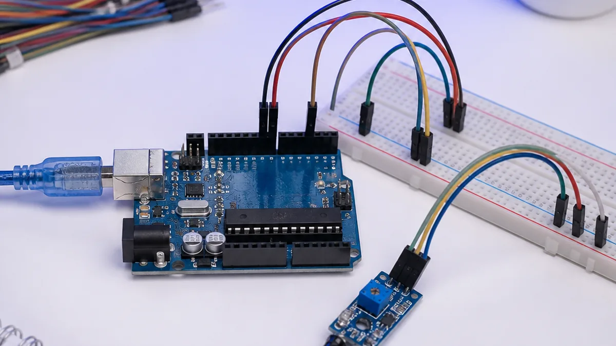
IR Sensor Arduino projects are one of the fastest ways to add obstacle and motion detection to an Arduino Uno build. In this guide we wire an IR sensor module to Arduino, load the IR sensor Arduino code, and test it in a Proteus simulation — so you can move straight from breadboard to real projects like counters, parking systems and line followers.
Welcome to this beginner-friendly Arduino tutorial on the ir. By the end of the guide, you'll wire the module to an Arduino UNO, flash a short sketch, and read live values on the Serial Monitor — no prior electronics experience required.
Need this built for you? I do custom Arduino, ESP32 and Proteus projects from $15.
What you'll learn
- How the module works in plain language
- The exact parts you need and how to wire them safely
- The full Arduino IDE sketch with comments
- Common issues and how to fix them
 — overview](/uploads/arduino/interfacing-ir-sensor-module-with-arduino/IR-Sensor-Cover.jpg)
 — wiring diagram](/uploads/arduino/interfacing-ir-sensor-module-with-arduino/IR-Sensor-Description.jpg)
Arduino code
Open the Arduino IDE, paste the sketch below into a new file, install any libraries the sketch #includes (Tools → Manage Libraries), select your board and COM port, then click Upload.
int IRSensor = 9; // connect ir sensor module to Arduino pin 9
int LED = 13; // conect LED to Arduino pin 13


void setup()
{
  Serial.begin(115200); // Init Serila at 115200 Baud
  Serial.println("Serial Working"); // Test to check if serial is working or not
  pinMode(IRSensor, INPUT); // IR Sensor pin INPUT
  pinMode(LED, OUTPUT); // LED Pin Output
}

void loop()
{
  int sensorStatus = digitalRead(IRSensor); // Set the GPIO as Input

  if (sensorStatus == 1) // Check if the pin high or not
  {
    // if the pin is high turn off the onboard Led
    digitalWrite(LED, LOW); // LED LOW
    Serial.println("Motion Ended!"); // print Motion Detected! on the serial monitor window
  }
  else
  {
    //else turn on the onboard LED
    digitalWrite(LED, HIGH); // LED High
    Serial.println("Motion Detected!"); // print Motion Ended! on the serial monitor window
  }
}
How it works
The sketch initialises serial communication and the ir driver in setup(), then in loop() it samples the sensor at a regular interval and prints the result to the Serial Monitor at 9600 baud. Open the Serial Monitor (Ctrl+Shift+M) after upload to see live readings.
Troubleshooting checklist
- No readings: verify the baud rate in Serial Monitor matches the sketch (usually 9600).
- Garbage characters: wrong baud rate or loose GND wire.
- Library not found: install the exact library referenced in the
#includeline via Library Manager. - Sensor not detected (I²C): run an I²C scanner sketch to confirm the address.
What to build next
Once the basic readout works, try logging values to an SD card, sending them over Wi-Fi with an ESP32, or pushing them to a Blynk IoT dashboard. Pair this module with our simulator round-up to prototype the circuit before soldering.
Stuck on your own build? Send me your Arduino / ESP32 / Proteus project on Fiverr — from $15, you don't pay if it doesn't work.
Frequently Asked Questions
Q.How do I connect an IR sensor to Arduino?
Wire the IR sensor module's VCC to Arduino 5V, GND to GND, and the OUT pin to any digital input such as D2. The module outputs LOW when an obstacle reflects the IR beam back and HIGH otherwise.
Q.What is the IR sensor Arduino code?
In setup() call pinMode(2, INPUT). In loop() read the pin with digitalRead(2) and turn on an LED or print to Serial when the value is LOW. Adjust the on-board potentiometer to set the detection distance.
Q.Why is my IR sensor always HIGH or always LOW?
The sensitivity trimmer is set too far in one direction, or ambient sunlight is saturating the receiver. Turn the potentiometer slowly until the indicator LED just switches, and shade the sensor from direct sunlight.
Q.Can I use the IR sensor module with 3.3V boards like ESP32?
Yes. Most FC-51 style IR modules accept 3.3–5V on VCC and their digital OUT is 3.3V-safe, so an ESP32 or ESP8266 can read the signal directly.
The Engineer Post
Embedded systems engineer and educator. Writes weekly tutorials at EmbedLab to help beginners ship real hardware.
Related projects
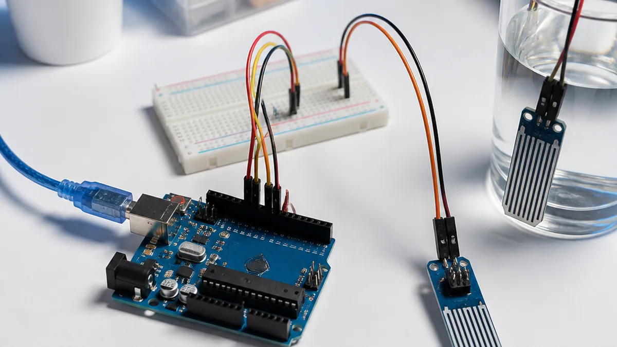
Water Level Sensor with Arduino
Step-by-step Arduino tutorial: wire the water level to an Arduino UNO, upload the example sketch, and read live values on the Serial Monitor.
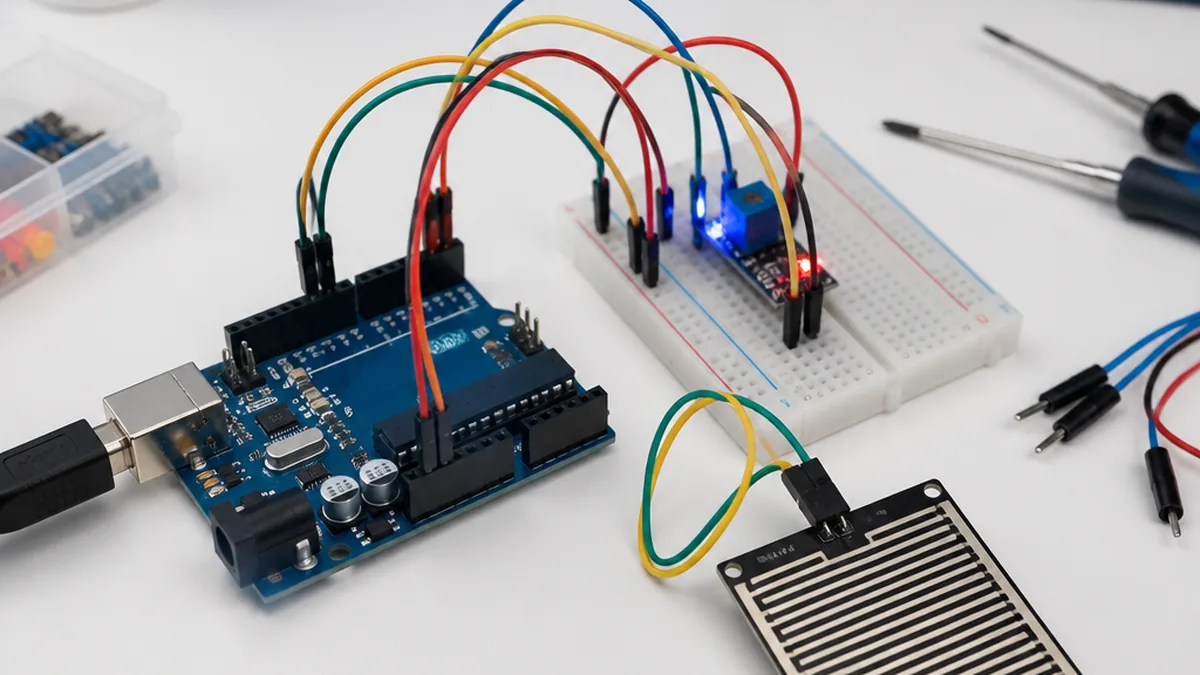
Rain Detection Sensor with Arduino
Step-by-step Arduino tutorial: wire the rain detection to an Arduino UNO, upload the example sketch, and read live values on the Serial Monitor.
Pulse Sensor with Arduino
Step-by-step Arduino tutorial: wire the pulse to an Arduino UNO, upload the example sketch, and read live values on the Serial Monitor.
MQ2 Combustible Gas Sensor with Arduino
Step-by-step Arduino tutorial: wire the mq2 combustible gas to an Arduino UNO, upload the example sketch, and read live values on the Serial Monitor.
 — Arduino UNO tutorial cover image](/uploads/arduino-covers/interfacing-the-sr04t-sr04m-waterproof-ultrasonic-sensor-with-arduino.webp)
Interfacing SR04T/SR04M Waterproof UltraSonic Sensor with Arduino Uno
Step-by-step Arduino tutorial: wire the the sr04t, sr04m waterproof ultrasonic to an Arduino UNO, upload the example sketch, and read live values on the Serial Monitor.