Arduino UNO Ultrasonic Project — HC-SR04 Distance Sensor with Free Arduino IDE Code
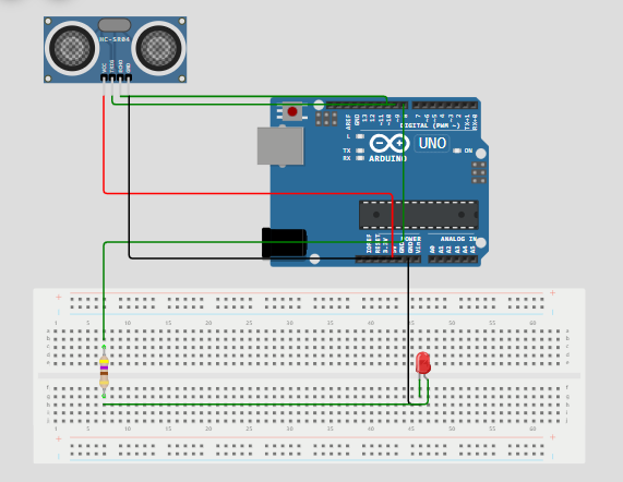
Ultrasonic Sensor
Arduino Ultrasonic projects help you measure distance and act on it. In this guide, you build a reliable Arduino Ultrasonic distance sensor with LED output. First, you get a clear parts list. Next, you get simple wiring steps. Then, you get the full sketch in WordPress code format. Also, you learn tests and fixes to avoid common errors. Finally, you get extension ideas to grow the project.
Project Summary
This Arduino Ultrasonic build uses an HC-SR04 or similar module. It measures distance in centimeters. Then, it lights an LED when an object sits closer than a set threshold. The code sends a short pulse. Afterwards, it reads the echo time and computes distance. Therefore, the project suits beginners and makers. Moreover, it fits small robots, parking sensors, and door guards.
Main Goals
- Measure distance using an ultrasonic transducer.
- Trigger an LED when an object crosses a threshold.
- Show how to wire sensors safely to Arduino.
- Provide a clean, copy-paste sketch in WordPress code format.
- Explain tests, issues, and simple fixes.
Parts List
Use common parts that you likely own. Also, you can find all parts in cheap kits. For that reason, this build stays low cost.
- Arduino Uno or compatible board.
- HC-SR04 ultrasonic sensor (or any ultrasonic module).
- Green LED and 220Ω resistor.
- Breadboard and jumper wires.
- USB cable for power and upload.
- Optional: small perf board for a permanent build.
How the Ultrasonic Sensor Works
The ultrasonic module sends a short sonic pulse. Then, the pulse hits an object and returns as an echo. Next, the Arduino measures the time between send and receive. The code converts time to distance. As a result, you get the object range in centimeters. Finally, you compare the range to a threshold to decide actions.
Signal Flow
First, digital pin triggers the trig pin for 10 microseconds. Second, the module sets the echo pin high for the return time. Third, pulseIn reads the echo duration. Fourth, you compute distance = duration × 0.034 / 2. Consequently, the number gives distance in cm.
Wiring Guide
Wire parts carefully to avoid errors. Also, make power and ground common. Next, double check pin numbers before upload.
- VCC of sensor to 5V on Arduino.
- GND of sensor to Arduino GND.
- Trig pin of sensor to digital pin 9.
- Echo pin of sensor to digital pin 10.
- LED long leg to digital pin 8 via 220Ω resistor.
- LED short leg to Arduino GND.
Also, place the sensor on a stable mount. Then, aim it so echoes return cleanly. Meanwhile, avoid direct sunlight on some modules. For that reason, test indoors first.
Pin Map and Notes
- Trig → D9 for pulse out.
- Echo → D10 for pulse in.
- LED → D8 with current limit resistor.
- Power → 5V stable supply from USB or regulator.
- Ground → Common ground across all parts.
If you use a 3.3V sensor, match the logic level or use a level shifter. Otherwise, most HC-SR04 modules work with 5V logic and need no shifter.
Sketch — WordPress Code Block
        // Define pin connections
        const int trigPin = 9;
        const int echoPin = 10;
        const int ledPin = 8;

        // Set a distance threshold for detecting movement (in cm)
        const int movementThreshold = 50; // Adjust this to your desired distance

        void setup() {

          // Initialize pin modes
          pinMode(trigPin, OUTPUT);
          pinMode(echoPin, INPUT);
          pinMode(ledPin, OUTPUT);

          // Start Serial Monitor for debugging
          Serial.begin(9600);
          Serial.println("Starting distance sensor...");
        }

        void loop() {

          // Trigger the sensor to send out a pulse
          digitalWrite(trigPin, LOW);
          delayMicroseconds(2);
          digitalWrite(trigPin, HIGH);
          delayMicroseconds(10);
          digitalWrite(trigPin, LOW);

          // Measure the duration of the pulse
          long duration = pulseIn(echoPin, HIGH);

          // Calculate distance (in cm)
          int distance = duration * 0.034 / 2;

          // Print distance to Serial Monitor for debugging
          Serial.print("Distance: ");
          Serial.print(distance);
          Serial.println(" cm");

          // Check if an object is within the threshold distance
          if (distance > 0 && distance <= movementThreshold) {
            Serial.println("Object detected within range. Turning LED on.");
            digitalWrite(ledPin, HIGH); // Turn on the LED
          } else {
            Serial.println("No object detected or out of range. Turning LED off.");
            digitalWrite(ledPin, LOW); // Turn off the LED
          }

          // Delay to avoid overwhelming the sensor
          delay(200);
        }
Upload and First Run
Open Arduino IDE and paste the sketch. Also, select the right board and COM port. Then, upload the code. Next, open Serial Monitor at 9600 baud. After that, watch distance values print every cycle. Finally, move an object in front of the sensor to test LED response.
Calibration and Thresholds
You can change movementThreshold to tune the trigger point. For example, set 20 for close detection. Also, set 100 to detect distant objects. Moreover, calculate the real measured distance and compare it to expected values. Then, adjust the threshold until detection matches your use case.
Tuning Steps
- Place a known object at 30 cm. Next, read the printed distance.
- Compare printed value to 30. Then, note the error value.
- Adjust threshold or add a small offset in code if needed.
- Repeat at 50 cm and 10 cm to verify linearity.
Testing Checklist
Test parts one at a time. First, test the Serial prints. Second, test LED control with a simple blink sketch. Third, test sensor pulses using a debug sketch. Then, combine all parts. Also, keep a logic probe or multimeter handy for troubleshooting.
Common Issues and Fixes
If readings are zero or NaN, check wiring and ground. Also, ensure trig and echo pins match the sketch. If the LED stays on, raise threshold or block near reflections. When readings jump, add a small median filter. For that reason, use three quick reads and take the middle value to avoid spikes.
Noise and False Echoes
Sometimes the sensor reads false echoes from nearby walls. To fix this, mount the sensor in a small tube to focus its beam. Also, add a shield to block side reflections. Meanwhile, test at different angles to find the cleanest echo path.
Power and Stability
If servos or extras draw power, avoid using the Arduino 5V rail. Instead, use a separate 5V regulator. Also, tie grounds together to keep references stable. In addition, place a 100 µF decoupling capacitor near the sensor power pins to smooth spikes.
Performance Tips
For faster response, reduce the delay between readings. However, do not set it too low. The sensor needs time to receive echoes at long ranges. Also, average several readings to get stable numbers. Meanwhile, print less to the serial monitor to keep the loop snappy.
Improving Range
To measure longer ranges, position the sensor away from obstructions. Next, use a reflector or a better transducer. In some cases, ultrasonic range extends well beyond 3 meters with strong transducers. For that reason, test different modules if you need extra range.
Use Cases for Arduino Ultrasonic
Ultrasonic sensors shine in many simple tasks. For instance, use them for parking sensors. Also, use them for obstacle detection in robots. Moreover, use them for liquid level checks in tanks. In addition, combine them with a buzzer to warn drivers in a garage. Finally, log distances to an SD card for a simple data logger.
Extend the Project
Add a small OLED display to show distance. Then, add a buzzer for audio alerts. Next, add WiFi to send readings to a phone. For remote logging, push values to a simple web server. Also, use several sensors to cover more spots. Finally, integrate with a motor driver for automated actions.
Safety and Best Practices
Ultrasonic sensors work with sound, not harmful waves. Still, keep units dry and away from dust. Also, avoid long continuous runs at max power. Instead, give the module short rest times. Moreover, secure the sensor in a case to protect it from knocks.
FAQ
Q: Can I use this on Arduino Nano? Yes, but remap pins if needed. Also, check available digital pins for trig and echo.
Q: Why does my sensor read inconsistent values? Try stable mounting and add a small median filter. Also, check for nearby reflective surfaces that cause ghost echoes.
Q: Does sunlight affect the sensor? No, ultrasonic sensors use sound, so sunlight has no effect. However, strong wind or open windows can affect readings.
Q: Can I use multiple sensors? Yes, but trigger them one at a time to avoid cross talk. For that reason, use a small delay or multiplexing scheme when you poll many sensors.
Project Checklist Before Publish
- Check the sketch compiles and uploads without errors.
- Verify serial output and LED behavior in tests.
- Ensure all wiring is secure and insulated.
- Mount the sensor to avoid side reflections.
- Document pin map and photo-graph the setup for your post.
Final Notes
This Arduino Ultrasonic guide gives a clear path from parts to a working sketch. Also, it stays light in words and simple in code. For that reason, you can copy the WordPress code block directly into your post. Moreover, you can expand the build with displays, WiFi, or logging. Finally, share your photos and notes to help others replicate your work.
The Engineer Post
Embedded systems engineer and educator. Writes weekly tutorials at EmbedLab to help beginners ship real hardware.
Related projects

Arduino UNO I2C Temperature Monitor — LCD, LM35 & Free Arduino IDE Code
Build an Arduino UNO I2C temperature monitoring project step by step: LM35 sensor, I2C LCD display, free Arduino IDE code and Arduino library — same wiring works for Arduino Nano, Arduino Mega and ESP32 Arduino.
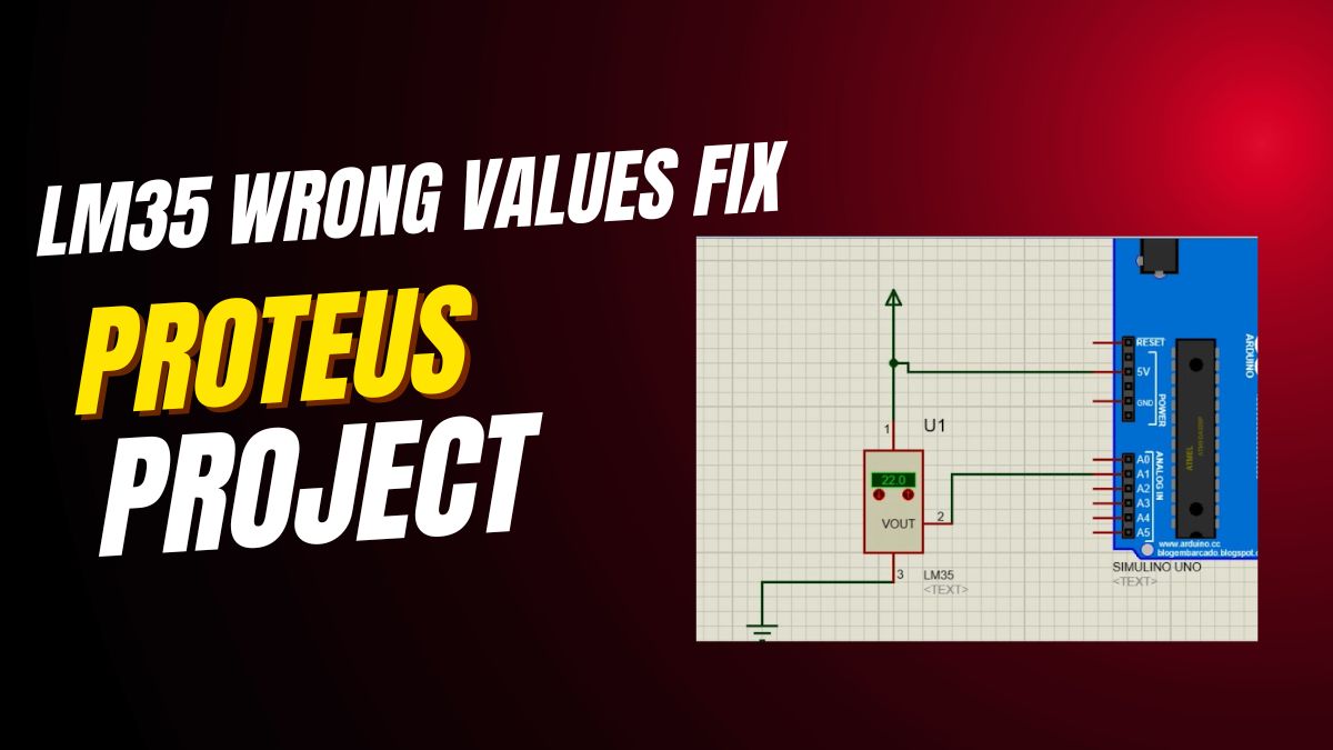
Fix LM35 Wrong Values on Arduino UNO — Free Arduino IDE Code & LCD Tutorial
How to fix LM35 wrong values on Arduino UNO: free Arduino IDE code, Arduino library, LCD display wiring and analog reference tips — also works for Arduino Nano, Arduino Mega and ESP32 Arduino temperature projects.
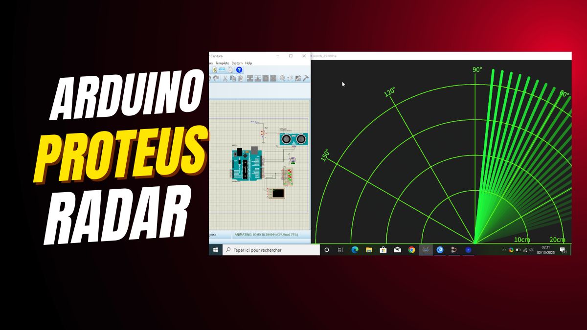
DIY Arduino UNO Radar with Ultrasonic Sensor — Free Arduino IDE Code & Servo
Build a DIY Arduino UNO radar with the HC-SR04 ultrasonic sensor, servo motor and Processing visualization: free Arduino IDE code and Arduino library — easily ported to Arduino Nano, Arduino Mega and ESP32 Arduino.
DIY Arduino UNO Radar — Ultrasonic Sensor, Servo & Free Arduino IDE Code
Build a DIY Arduino UNO radar with the HC-SR04 ultrasonic sensor, a servo motor and Processing visualization: free Arduino IDE code and Arduino library — also works on Arduino Nano, Arduino Mega and ESP32 Arduino.

Interface SPI EEPROM with Arduino UNO — Free Arduino IDE Code & Library
How to interface an SPI EEPROM with Arduino UNO step by step: free Arduino IDE code, Arduino library, full wiring map — easily ported to Arduino Nano, Arduino Mega and ESP32 Arduino.