Arduino UNO I2C Temperature Monitor — LCD, LM35 & Free Arduino IDE Code


Arduino I2C Temperature Project
Want to send real-time temperature data between two Arduino boards? Then you need Arduino I2C communication. This easy-to-follow tutorial shows you how to build a master-slave temperature monitoring system using the I2C protocol. You’ll learn wiring, coding, and how to control an LED based on temperature. Whether you’re new to Arduino or looking to expand your skills, this guide gives you everything you need.
Why Use I2C for Arduino Temperature Projects?
I2C (Inter-Integrated Circuit) is a smart choice for Arduino projects because it uses only two wires: SDA (data) and SCL (clock). Moreover, it lets one Arduino (the master) talk to one or more other devices (slaves). Therefore, you save pins and keep your setup clean.
For temperature monitoring, I2C is perfect. It supports multiple sensors, works over short distances, and handles real-time data well. In addition, the Arduino Wire library makes coding simple. As a result, you can focus on building, not debugging.
Key Benefits of Arduino I2C Communication
First, I2C uses just two pins—A4 (SDA) and A5 (SCL) on most Arduino Uno boards. Second, you can connect many devices to the same bus. Third, wiring stays neat, which reduces errors. Finally, the protocol includes built-in error checking, so your data stays reliable.
Parts You’ll Need for This I2C Arduino Project
Before you start coding, gather these components. Fortunately, most are common in starter kits.
- 2 Arduino Uno boards (or compatible like ELEGOO Uno R3)
- 1 analog temperature sensor (LM35 or TMP36)
- 1 LED
- 1 resistor (220Ω)
- Breadboard and jumper wires
- 2 USB cables
- Optional: 4.7kΩ pull-up resistors for SDA and SCL (if needed)
Note: ELEGOO boards are not official Arduino but work with the Arduino IDE and cost less. Also, always double-check your sensor type—LM35 and TMP36 have slightly different formulas.
Wiring the Two Arduinos for I2C Communication
Now, connect your master and slave Arduinos correctly. After that, your system will run smoothly.
Step-by-Step I2C Wiring Instructions
First, link the I2C bus between both boards. Connect Master A4 to Slave A4 (SDA). Then, connect Master A5 to Slave A5 (SCL). Also, connect the GND pins of both Arduinos together. This shared ground is essential for stable communication.
Next, wire the temperature sensor to the master Arduino. Attach the sensor’s signal pin to A1, VCC to 5V, and GND to Arduino GND.
After that, set up the LED on the slave Arduino. Connect the LED’s long leg (anode) to pin 13 through a 220Ω resistor. Then, connect the short leg (cathode) to GND.
Finally, plug both Arduinos into your computer using USB cables. Power comes from USB, so no external supply is needed for this demo.
💡 Pro Tip: If your I2C data seems glitchy, add 4.7kΩ pull-up resistors from SDA to 5V and SCL to 5V. Many modern boards include these internally, but older ones may not.
Arduino I2C Code for Temperature Data Transfer
With wiring done, it’s time to upload code. Below are two sketches: one for the master (sends temperature) and one for the slave (receives and controls LED).
Master Arduino Code (Temperature Sender)
#include <Wire.h>

#define SENSOR_PIN A1
#define SLAVE_ADDRESS 8

void setup() {
  Wire.begin();              // Start I2C as master
  Serial.begin(9600);        // For debugging
}

void loop() {
  int sensorValue = analogRead(SENSOR_PIN);
  float voltage = sensorValue * (5.0 / 1023.0);
  int temperature = (voltage - 0.5) * 100; // LM35 formula (°C)

  Wire.beginTransmission(SLAVE_ADDRESS);
  Wire.write(temperature >> 8);     // Send high byte
  Wire.write(temperature & 0xFF);   // Send low byte
  Wire.endTransmission();

  Serial.print("Temperature: ");
  Serial.println(temperature);
  delay(1000); // Wait 1 second
}
Slave Arduino Code (LED Controller)
#include <Wire.h>

#define LED_PIN 13
#define SLAVE_ADDRESS 8
#define TEMP_THRESHOLD 30  // °C

void setup() {
  Wire.begin(SLAVE_ADDRESS);      // Start I2C as slave
  Wire.onReceive(receiveEvent);   // Call function when data arrives
  Serial.begin(9600);
  pinMode(LED_PIN, OUTPUT);
}

void receiveEvent(int bytes) {
  // Rebuild 16-bit integer from two bytes
  int temperature = (Wire.read() << 8) | Wire.read();

  Serial.print("Received Temperature: ");
  Serial.println(temperature);

  // Turn LED on if temp > 30°C
  digitalWrite(LED_PIN, temperature > TEMP_THRESHOLD ? HIGH : LOW);
}

void loop() {
  delay(100); // Keep loop alive
}
How the Arduino I2C Code Works
The master reads the analog sensor value, converts it to voltage, then to Celsius. Because I2C sends one byte at a time, it splits the temperature (a 16-bit integer) into two bytes: high and low. Then it transmits both.
The slave listens for incoming data. When it gets two bytes, it reassembles them into the full temperature value. After that, it checks if the value exceeds 30°C. If so, it turns the LED on. Otherwise, it turns the LED off. Meanwhile, both boards print data to the Serial Monitor for debugging.
Testing Your I2C Arduino Temperature System
Once everything is wired and coded, test the system. Follow these steps to ensure success.
Step-by-Step Testing Guide
First, upload the master code to one Arduino and the slave code to the other. Make sure you select the correct board and port in the Arduino IDE.
Next, open two Serial Monitor windows—one for each Arduino. Set both to 9600 baud. You should see temperature values printed every second on the master side.
Then, watch the slave’s Serial Monitor. It should show “Received Temperature: [value]” each time data arrives.
Now, warm the sensor with your fingers. Within seconds, the temperature should rise above 30°C. At that point, the LED on the slave Arduino should light up. If it doesn’t, double-check your wiring and code.
💡 Troubleshooting Tip: If no data appears, verify the I2C address (we used 8). Also, ensure SDA and SCL aren’t swapped. Finally, confirm both Arduinos share a common GND.
Real-World Uses for This Arduino I2C Project
This simple setup opens doors to many smart applications. For example, you can expand it into a home automation system. Imagine placing temperature sensors in different rooms. Then, a central Arduino collects all data via I2C and triggers fans or alerts.
Likewise, you could add more slaves—like one for humidity, another for motion. Because I2C supports multiple addresses, each slave responds only to its own data. Thus, your system stays organized and scalable.
Another idea: log temperature data to an SD card connected to the master. Or send alerts to your phone using a Wi-Fi module on the slave side. The possibilities grow once you master I2C basics.
Common Mistakes to Avoid in Arduino I2C Projects
Even experienced makers run into issues. However, you can avoid most problems with these tips.
First, never forget the shared GND. Without it, voltage levels differ, and communication fails. Second, don’t mix up SDA and SCL. They look similar but serve different roles. Third, always use the same I2C address in both master and slave code.
Additionally, analog sensors like LM35 need clean power. Noise from motors or LEDs on the same board can distort readings. So, power them separately if possible. Lastly, remember that I2C has speed and distance limits—keep wires under 30 cm for best results.
Final Thoughts on Mastering Arduino I2C Communication
In summary, this Arduino I2C temperature project teaches core skills: wiring, two-board communication, and real-time data handling. Because I2C is widely used in sensors and displays, learning it now prepares you for advanced builds.
Start small, test often, and expand slowly. Before you know it, you’ll design your own smart home or industrial monitor. So grab your Arduinos, follow this guide, and unlock the power of I2C today!
Got questions? Drop them in the comments. And if this helped, share it with a fellow maker!
Embedded Electronics — Home
Build an Arduino Calculator with LCD Keypad
Arduino Calculator Project
Smart Parking System with Arduino
5 Simple Arduino Projects for Beginners
Arduino Multiplexer LED Projects
Arduino Traffic Light System
Arduino 7-Segment Display Project
Arduino Interrupts: Button + LED Control
The Engineer Post
Embedded systems engineer and educator. Writes weekly tutorials at EmbedLab to help beginners ship real hardware.
Related projects
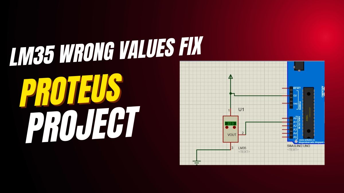
Fix LM35 Wrong Values on Arduino UNO — Free Arduino IDE Code & LCD Tutorial
How to fix LM35 wrong values on Arduino UNO: free Arduino IDE code, Arduino library, LCD display wiring and analog reference tips — also works for Arduino Nano, Arduino Mega and ESP32 Arduino temperature projects.
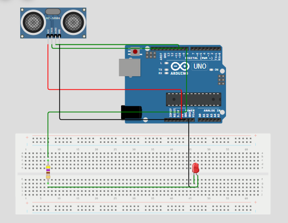
Arduino UNO Ultrasonic Project — HC-SR04 Distance Sensor with Free Arduino IDE Code
Build an Arduino UNO ultrasonic distance project with the HC-SR04 sensor and LCD display: free Arduino IDE code and Arduino library — easily ported to Arduino Nano, Arduino Mega and ESP32 Arduino.
30+ Arduino UNO Projects for Beginners — Free Arduino IDE Code, LED & LCD
30+ beginner Arduino UNO projects with free Arduino IDE code, Arduino library examples, LED and LCD circuits, plus Arduino Nano, Arduino Mega and ESP32 Arduino tutorials — perfect first Arduino project ideas to download and build today.
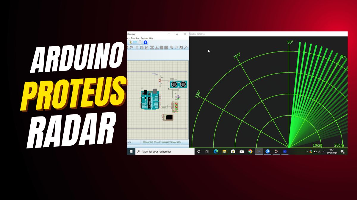
DIY Arduino UNO Radar — Ultrasonic Sensor, Servo & Free Arduino IDE Code
Build a DIY Arduino UNO radar with the HC-SR04 ultrasonic sensor, a servo motor and Processing visualization: free Arduino IDE code and Arduino library — also works on Arduino Nano, Arduino Mega and ESP32 Arduino.
DIY Arduino UNO Radar with Ultrasonic Sensor — Free Arduino IDE Code & Servo
Build a DIY Arduino UNO radar with the HC-SR04 ultrasonic sensor, servo motor and Processing visualization: free Arduino IDE code and Arduino library — easily ported to Arduino Nano, Arduino Mega and ESP32 Arduino.